متاسفانه نتوانستیم کالای مرتبطی را برای شما پیدا کنیم!
- abcd efgh ijkl mnop qrst uvwx yz

Employer needs:
This project is related to an industrial place that requires a comprehensive protection and security system for the transmission of image, data and sound on the optical fiber substrate.
Also, because there is a high sensitivity to the preservation of the recorded images, therefore, the employer wants to be able to record the images as a backup in addition to the management room, the security room as well as the monitoring. Therefore, according to the need, it was decided to monitor and record images separately in this main colon.
Also, the employer wants to transfer voice and internal network between these two points.
Zoning:
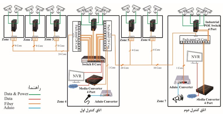
Considering the distances between the cameras and considering the two main areas for monitoring, we have considered a total of 7 areas in our zoning. Zone 4 is the main control room and zone 7 is the second control room.
Before designing the cabling, it is necessary for the employer to buy his own 24-core cable. There are different methods for cabling design, but according to the needs of the employer and the spaces that exist as control rooms, and according to the available cables, and also to reduce costs and foresight, it is better to choose zone 4 (the main control room) as the cabling center. be and be needed. A 24-core cable is used from the right side (for zones 5, 6, and 7) and a 24-core cable is used from the left side (for zones 1, 2, and 3).
For this purpose, we consider two patch panels in the main control room, one for the left side and the other for the right side. Cabling method is cut and transit and star model. On the left side, cable 24 enters zone 3 and 8 cores are implemented, and the rest of the cores continue for zone 2, and in the same way, 8 cores are implemented for zone 2 and zone 1.
The right side is implemented in the same way for zones 5 and 6 with 4 cores and zone 7 with 16 cores.
We can consider 8 cores for each zone for the right zones as well as the left side, but because there are many optical fiber connections between the two control rooms, i.e. zones 4 and 7, we preferred to have 16 communication cores. Between these two points, in addition to camera data, voice and internal network data are transmitted over the fiber, and in the future, other communications such as telephone may be added.
Because there are at least two cameras in each zone, we have used a four-port industrial switch that has four gigabit POE ports and two SFP ports. These switches in all zones send their data to the 8-port switch in the main control room (zone 4) through the SFP port.We connect 8 port of the switch to the NVR to record images.
As mentioned above, the client's requirement was that all the images, in addition to being recorded in the main control room, should also be recorded and monitored in the second control room. After the other uplink of our switch, we give the image data to a 4-port media converter so that through this media converter the data of the cameras on the fiber substrate is sent to the second control room. The reason for using this 4-port media converter is that the internal network data can be sent through the same media converter and there is no need to use another media converter.
According to the client's requirement, we have used an audio fiber optic converter for audio transmission to establish audio communication between the two control rooms.
Advantages of this type of design:
Foresight due to the existence of empty cores, lack of excessive complexity, easy troubleshooting, optimal use of equipment and cables, low design cost